Half adder circuit ,theory and working. truth table , schematic realization Full adder : circuit diagram, truth table, equations & verilog code Binary adder and subtractor circuits: half and full adder, subtractor
Full Adder - Truth table & Logic Diagram | Electricalvoice
Draw the logic diagram of a full adder. create a 2-bit adder-subtractor
Adder bit circuit adders gate sum expressions implement
Adder subtraction binaryAdder diagram block circuit gates using basic truth table Adder nand truth table diagram logic using gate minimum numberAdder 6m subtractor circuit cssimplified jun2006 logic.
Virtual labsAdder circuit derive 4 bit full adder circuit, truth table and symbol. implement 4 bitAdder circuit construction binary vidi gupta sourav.
![Full Adder : Circuit Diagram, Truth Table, Equations & Verilog Code](https://i2.wp.com/www.watelectronics.com/wp-content/uploads/Full-Adder-Block-Diagram-.jpg)
Combinational logic circuits : definition, examples, and applications
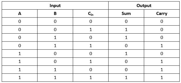
Adder combinational logic circuitsWhat is half adder and full adder circuit? Adder block iitrFull adder : circuit diagram, truth table, equations & verilog code.
Adder truth table diagram logic circuit shown figureFull adder Adder half truth table schematic circuit bit binary xor inputs realization outputs gates show difference between numbers diagram logic norHalf adder circuit: theory, truth table & construction.
![Adder - Classifications, Construction, How it Works and Applications](https://i2.wp.com/electricalfundablog.com/wp-content/uploads/2020/01/Full-Adder-Truth-Table1_thumb.jpg)
Adder half circuit carry ripple bit schematic diagram gate truth table delay electronics xor doubt without representation shown single below
Full adder circuit, truth table and verilog codeBinary adder and subtraction circuits along with its various types Full adder circuit: theory, truth table & constructionAdder circuit diagram gates truth table using code verilog basic.
Full adderAdder truth table subtractor binary diagram carry block back Adder circuit construction binary circuits ibm sourav guptaSolved 4) draw the full-adder truth table and derive a.
![Half adder circuit ,theory and working. Truth table , schematic realization](https://i2.wp.com/www.circuitstoday.com/wp-content/uploads/2012/03/half-adder-truth-table-schematic-realization.png)
![Binary Adder and Subtractor Circuits: Half and Full Adder, Subtractor](https://i2.wp.com/www.electronicshub.org/wp-content/uploads/2015/06/Full-adder-truth-table.jpg)
![Half Adder Circuit: Theory, Truth Table & Construction](https://i2.wp.com/circuitdigest.com/sites/default/files/projectimage_tut/Half-Adder-Circuit-and-Its-Construction.png)
![Full Adder : Circuit Diagram, Truth Table, Equations & Verilog Code](https://i2.wp.com/www.watelectronics.com/wp-content/uploads/Full-Addder.jpg)
![Binary Adder and Subtraction Circuits Along With Its Various Types](https://i2.wp.com/www.watelectronics.com/wp-content/uploads/Full-Adder-Truth-Table.jpg)
![Solved 4) Draw the Full-Adder Truth Table and derive a | Chegg.com](https://i2.wp.com/d2vlcm61l7u1fs.cloudfront.net/media/36d/36dc3264-74a3-4599-85aa-07ab69f472f1/phpXfH6Ve.png)
![Full Adder - Truth table & Logic Diagram | Electricalvoice](https://i2.wp.com/electricalvoice.com/wp-content/uploads/2018/05/full-adder-using-NAND-gate1.jpg)
![Full Adder Circuit: Theory, Truth Table & Construction](https://i2.wp.com/circuitdigest.com/sites/default/files/projectimage_tut/Full-Adder-Circuit.png)
![4 bit FULL ADDER circuit, truth table and symbol. IMPLEMENT 4 bit](https://i2.wp.com/www.fullchipdesign.com/media/wpimages/full_adder.png)
![Full Adder - Truth table & Logic Diagram | Electricalvoice](https://i2.wp.com/electricalvoice.com/wp-content/uploads/2018/05/full-adder-truth-table.jpg)