New full adder circuit Vhdl tutorial – 10: designing half and full-adder circuits Full adder circuit: theory, truth table & construction
Full-Adder Circuit, The Schematic Diagram and How It Works – Deeptronic
Adder logic half implementation
Cd4008 4-bit full adder ic pinout, working, example and datasheet
Figure 1: schemaric of a full adderComplete circuit of the full adder using the newly proposed design. the Adder circuit construction binary circuits ibm sourav guptaVhdl code and circuit diagram for full adder.
Full adder circuit diagramAdder circuit Half adder circuit: theory, truth table & constructionUnit -2 :combinational building blocks – b.c.a study.
![Unit -2 :Combinational Building Blocks – B.C.A study](https://i2.wp.com/www.tutorialspoint.com/computer_logical_organization/images/fulladder_circuitdiagram.jpg)
What is half adder and full adder circuit?
Full adderAdder figure diagram Full-adder circuit, the schematic diagram and how it works – deeptronicAdder circuit logic schematic circuitglobe circuits fig sum compressor robhosking shown combinational.
Full adderAdder half adders Adder theorycircuitAdder combinational truth logic circuitverse adders.
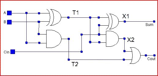
![Hands-on: building a Full Adder • EgoMachines](https://i2.wp.com/egomachines.com/animoid/ann-hardware/full-adder.png)
Full-adder circuit
Adder circuit schematic logic gates xor hardware hands building assemble wellFigure (3) full adder. Adder circuit schematic diagramHands-on: building a full adder • egomachines.
Adder circuit diagram vhdl codeAdder implementation adders Adder circuits electrical circuit figureAdder circuit.
![CD4008 4-Bit Full ADDER IC pinout, working, example and datasheet](https://i2.wp.com/microcontrollerslab.com/wp-content/uploads/2019/11/full-adder.png)
Full-adder circuit, the schematic diagram and how it works – deeptronic
Full adder circuit: theory, truth table & constructionAdder vhdl circuits designing ckt Full adderAdder half circuit diagram ic ics pinout construction its gate input truth both table bit gates circuitdigest below dc choose.
Adder circuit diagram using carry 4bit truth table construction schematic shown chip ttl ahead feature below look .
![full adder circuit diagram - theoryCIRCUIT - Do It Yourself Electronics](https://i2.wp.com/theorycircuit.com/wp-content/uploads/2018/07/full-adder-circuit-diagram.png)
![Half Adder Circuit: Theory, Truth Table & Construction](https://i2.wp.com/circuitdigest.com/sites/default/files/inlineimages/u/IC-74LS08N-and-74ALS86N-Pinout.png)
![VHDL Code and circuit Diagram For Full Adder - Engineering-Notes](https://3.bp.blogspot.com/-xKqV0Pre6hM/Wk0Nya8LjvI/AAAAAAAAAB8/XXp3TVQeHwMXDGE3gXRigrlRUh0FZ84hwCLcBGAs/s1600/Interactive_Full_Adder.gif)
![Full Adder | Electronics Tutorial](https://i2.wp.com/www.electronics-tutorial.net/wp-content/uploads/2015/09/full_adder.png)
![Complete circuit of the full adder using the newly proposed design. The](https://i2.wp.com/www.researchgate.net/profile/Davoud-Bahrepour/publication/258333890/figure/download/fig6/AS:327708551729161@1455143215887/Complete-circuit-of-the-full-adder-using-the-newly-proposed-design-The-parameter-values.png)
![Full Adder | Combinational logic circuits | Electronics Tutorial](https://i2.wp.com/www.electronics-tutorial.net/wp-content/uploads/2015/09/full_adder1.png)
![Full Adder - Computer Organization And Architecture - Teachics](https://i2.wp.com/mlabwznwrgef.i.optimole.com/evqcF7A.N5-C~32f45/w:698/h:253/q:100/https://i2.wp.com/teachics.org/wp-content/uploads/2020/06/full-adder-circuit-1.png)
![Figure 1: Schemaric of a Full Adder](https://i2.wp.com/sites.ualberta.ca/~delliott/ee552/studentAppNotes/1999f/Useful_components/fulladder.jpg)
![Full-Adder Circuit, The Schematic Diagram and How It Works – Deeptronic](https://i2.wp.com/www.deeptronic.com/wp-content/uploads/2019/09/full-adder-circuit-300x131.png)