Adder circuit combinational ha sequential Flop flops Counter synchronous bit diagram circuit electronics
Parity Generator and Parity Checker
8 bit alu circuit
Low-cost 6-bit dac circuit diagram
Circuit majority bit circuitlab description4 bit down counter Simplified circuit diagram of 8-bit crt dac😊 four bit parallel adder. 4 bit binary adder circuit / block diagram.
Adder circuit diagram schematic bit works figureFull-adder circuit, the schematic diagram and how it works – deeptronic 6.4: 2-bit adder circuitParity even checker odd technobyte.
![Parity Generator and Parity Checker](https://i2.wp.com/technobyte.org/wp-content/uploads/2019/10/4-bit-even-parity-generator-circuit.png?resize=555%2C389&ssl=1)
Circuit diagram of 3-bit synchronous counter
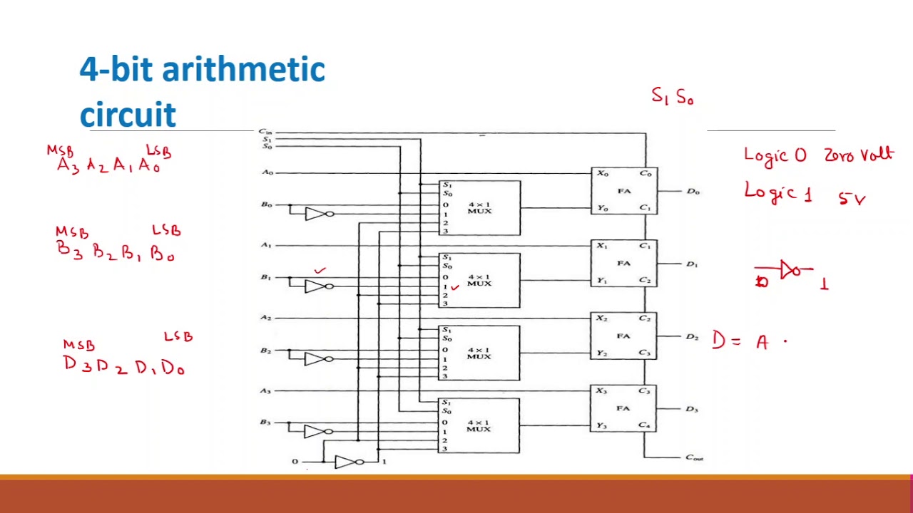
Design of 4 bit arithmetic circuitAdder bit subtractor circuit carry ripple diagram logic using project build only digital computing learn let its indie electronics Let's learn computing: 4 bit adder/subtractor circuit4 bit alu circuit diagram.
Circuit diagram supply power seekic million bit dataAdder bit parallel four circuit binary diagram logic subtractor digital block example geeksforgeeks detailed discussion Arithmetic alu 4bit performsBit circuit.
![Index 31 - Circuit Diagram - SeekIC.com](https://i2.wp.com/www.seekic.com/uploadfile/ic-circuit/s201412323859650.gif)
Counter bit down circuit diagram digital
Parity generator and parity checkerCircuit dac bit diagram cost low fig electronics State diagram and implementation of a six bit ring counter with dThree bit flash analog to digital converter circuit.
Circuit bit digital converter flash analog three diagram circuits analogue voltage divider used gr nextMajority 3-bit circuit Arithmetic logic unit png : the arithmetic and logic unit performs all5 logic circuits.
Circuit diagram bit drive ccpd supporting 1024 seekic
Two bit alu circuit design with instructions to read and understand theAdder bit logic four circuits figure x64 sonoma cs bob edu Combinational and sequential design of a 4-bit adder. (a) ha circuitAdder adders libretexts circuits pageindex.
.
![State diagram and implementation of a six bit ring counter with D](https://i2.wp.com/www.researchgate.net/profile/Zivko_Kokolanski/publication/322106955/figure/download/fig2/AS:576721952796672@1514512636172/State-diagram-and-implementation-of-a-six-bit-ring-counter-with-D-Flip-flops.png)
![Full-Adder Circuit, The Schematic Diagram and How It Works – Deeptronic](https://i2.wp.com/www.deeptronic.com/wp-content/uploads/2019/09/4-bit-adder-circuit.png)
![😊 Four bit parallel adder. 4 bit Binary adder circuit / block diagram](https://i2.wp.com/www.geeksforgeeks.org/wp-content/uploads/full_adder.png)
![Design of 4 Bit Arithmetic Circuit - YouTube](https://i.ytimg.com/vi/IOq1fhGAjqU/maxresdefault.jpg)
![Combinational and sequential design of a 4-bit Adder. (a) HA circuit](https://i2.wp.com/www.researchgate.net/profile/Ebrahim_M_Songhori/publication/283633559/figure/fig2/AS:363942875549699@1463782151965/Combinational-and-sequential-design-of-a-4-bit-Adder-a-HA-circuit-b-FA-circuit-c.png)
![circuit diagram of 3-bit synchronous counter - Electronics Coach](https://i2.wp.com/electronicscoach.com/wp-content/uploads/2019/08/circuit-diagram-of-3-bit-synchronous-counter.jpg)
![two bit alu circuit design with instructions to read and understand the](https://i.pinimg.com/originals/95/09/07/95090768e2e9517770f5ce3134d32337.jpg)
![6.4: 2-Bit Adder Circuit - Engineering LibreTexts](https://i2.wp.com/eng.libretexts.org/@api/deki/files/41933/2_bit_full_adder_circuit.png?revision=1&size=bestfit&width=654&height=789)
![Arithmetic Logic Unit Png : The arithmetic and logic unit performs all](https://i2.wp.com/img.favpng.com/5/9/21/arithmetic-logic-unit-4-bit-circuit-diagram-wiring-diagram-png-favpng-5NsfXcctjzURRAUvpEAr4HNdw.jpg)